Filler and capper matched together
The filling method, container stability and line speed affect the capping machinery and conveyor layout.
Complete lines
Complete bottle machinery planning for filling, cap feeding, capping, labelling, coding, conveyors and production line upgrades.
Specification focus
Use this page to narrow the specification around this bottle machinery family before requesting a quote.
The filling method, container stability and line speed affect the capping machinery and conveyor layout.
A complete bottle line may include label application, batch coding, inspection and packing flow after the capper.
Operator access, cap replenishment, maintenance space, utilities and cleaning routines should be considered before equipment is ordered.
Relevant equipment
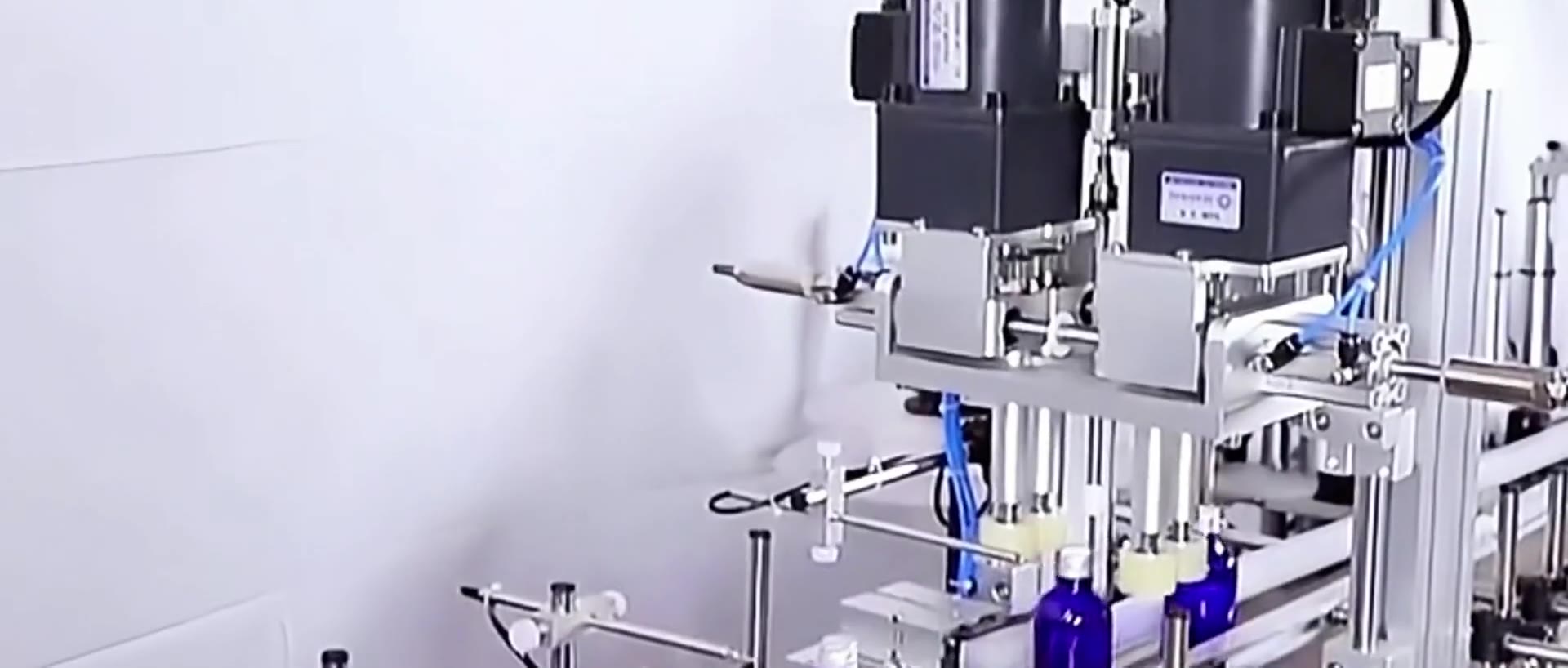
Bottle machinery
Integrated bottle machinery layouts covering filling, capping, cap handling, labelling, coding and conveyors.
Before you ask for a quote
For an accurate recommendation, supply bottle and closure samples or photographs, target output, batch sizes, fill product, bottle dimensions, cap dimensions and notes on any existing line equipment.
| Closure / cap type | Typical machine route | Specification checks |
|---|---|---|
| Threaded plastic screw cap | Screw capper, chuck capper, belt or spindle capper | Torque repeatability, cap height, bottle grip, thread start, changeover time |
| Aluminium ROPP closure | Semi-automatic, automatic or multi-head ROPP capper | Bottle neck finish, skirt length, tamper band, glass stability, roller tooling |
| Pump or lotion pump | Pump bottle capping machine with tube control | Dip-tube length, orientation, cap presentation, bottle stability, tightening torque |
| Trigger sprayer | Trigger sprayer bottle capping machine | Head orientation, tube handling, product sector, container neck and bottle shape |
| Push-on or snap cap | Press capping machine with cap feeder | Vertical force, closure fit, bottle support, cap nesting and feeder orientation |
FAQs
A line can include bottle infeed, filling, cap feeding, capping, labelling, coding, conveyors, accumulation and packing support.
Often yes, but conveyor height, speeds, bottle spacing and controls must be reviewed.
Send bottle and cap details, line speed target and photographs of the current production area. Lancing can advise on the most suitable bottle capping machine or complete line route.
Integrated process definition
The slowest or least stable operation sets the real line output. Filling cycle, settling or drip control, cap presentation, tightening, inspection and downstream accumulation must therefore be considered together, with a clear definition of what counts as a good bottle.
| Process area | Specification inputs | Line consequence |
|---|---|---|
| Filling | Product, viscosity, foam, fill volume, accuracy requirement, nozzle count, cleaning and product supply. | Determines bottle dwell, spacing, product condition at the neck and the release pattern to the capper. |
| Closure placement | Manual or automatic feeding, cap orientation, dip tubes, liner, tamper feature and refill method. | May set sustained output and required buffer even when the capping head can cycle faster. |
| Capping | Closing method, torque or forming criteria, bottle support, change parts and reject checks. | Determines pack quality, bottle handling and the interface to inspection or labelling. |
| Conveying | Bottle base, height, centre of gravity, conveyor height, speed range, guides and accumulation. | Controls transfer stability, pressure between bottles and recovery from blocked or starved conditions. |
| Controls and safety | Start/stop logic, faults, emergency stops, guarding interfaces, permissives and existing-machine signals. | Defines how the complete line stops, restarts and protects operators without producing uncontrolled bottles. |
Acceptance evidence
Agree each bottle, closure and product condition that will be demonstrated, including the worst-case format.
Define run duration, accepted bottle count, normal replenishment and how planned or unplanned stops are treated.
Record fill result, cap height, torque or opening performance, leakage, visible damage, missing caps and rejects.
Demonstrate bottle transfer, blocked and starved logic, controlled restart, recipes and agreed signals to other equipment.
A factory test can verify the equipment available at the supplier’s premises. Site acceptance should address final utilities, product supply, line interfaces, installation conditions and the agreed production handover. Neither should rely on an undefined phrase such as “runs at speed”.
Review bottle machinery interfaces, cap feeding and automatic capping, then provide the complete scope through the quotation checklist.
Filling and capping line FAQ
The limiting operation can change by product and format. Filling dwell, cap feeding, capping quality, labelling stability, operator replenishment or downstream packing may each set sustained good output.
Counting only machine cycles can hide rejects, missing caps, spills, stops and bottles awaiting rework. Accepted finished bottles provide a clearer basis for production capacity.
Blocked testing checks the response to a stopped downstream process; starved testing checks loss of incoming bottles or caps. The line should stop and restart without uncontrolled pressure, spills, damaged packs or a surge of defects.
Yes, where conveyor height, bottle transfer, speed range, control signals, safety boundaries, accumulation and physical layout can be agreed. Details of the existing machine are needed before the interface is fixed.
Factory acceptance tests the agreed equipment and samples before delivery where included. Site acceptance addresses the installed system, final utilities, actual interfaces and the agreed production conditions at the customer site.
Provide products, fill volumes, bottles, caps, labels, output, formats, layout, utilities, existing equipment, cleaning expectations, quality checks, operator assumptions and the preferred project acceptance route.
Accepted-output line balance
A filling and capping line can only sustain the output of its most restrictive operating condition. That restriction may be bottle spacing from the filler, cap replenishment, closure placement, the time needed to stabilise a soft container, downstream inspection or the accumulation available during a short stop. The line study should therefore follow the bottle from filler discharge to the next accepted process.
| Line interface | Questions for the project scope | Acceptance evidence |
|---|---|---|
| Filler discharge to capper infeed | What bottle pitch, conveyor height and discharge pattern are expected? Are containers wet, foamy, flexible or unstable after filling? | Representative transfer at normal fill condition, including gaps, restart and the least stable bottle format. |
| Cap supply to placement point | Who supplies the hopper, feeder, chute, low-level response, escapement and format tooling? | Correctly oriented cap supply through normal loading, low level, blocked demand and restart. |
| Placement to tightening or forming | How is the cap held square, the bottle supported and the required torque, top pressure or roller action applied? | Cap height, thread or band condition, opening or torque checks, leakage, orientation and visible finish. |
| Capping to inspection or labelling | Which defects are checked, where can a bottle be rejected and how much accumulation is available before the capper stops? | Challenge tests where inspection is included, controlled reject handling and stop/restart without bottle pressure damage. |
| Controls and safety boundary | Which machine is line master, what ready/fault/blocked signals are exchanged and where are guarding and emergency-stop responsibilities divided? | Documented sequence, safe stop, reset, restart and clear status for the operator and commissioning team. |
| Changeover and cleaning | Which parts, settings, recipes and cleaning steps apply across the filler, capper, feeder and conveyors? | Complete agreed format change, first-off approval and confirmation that access and tooling storage support the procedure. |
Factory and site acceptance boundaries
Factory acceptance can demonstrate the supplied machinery with agreed samples, utilities and a defined test arrangement. Site acceptance may additionally depend on the production product, permanent services, room layout, upstream and downstream equipment, operator practices and final controls integration. The quotation should separate these conditions so that an untested site dependency is not treated as a machine result.
Record the machines, temporary conveyors, samples, tooling, settings, utilities and software state used for the agreed factory test.
Record run duration, accepted output, replenishment, planned stops, quality checks, interventions and the limits of any simulated interface.
Identify permanent conveyors, product supply, air and electrical services, floor levels, extraction, networking and third-party machine signals.
Agree installation checks, operator training, changeover demonstration, documents, spares and the method for closing remaining actions.
Use the automatic capper recovery guide and cap-feeder test sequence when defining the line test. Put the complete boundary into the quotation checklist before comparing proposals.
Integrated-line proof
A filling and capping project can contain individually capable machines yet still fail to sustain production if bottle spacing, cap availability, accumulation or state signals are not coordinated. The final scope should describe the interfaces and the conditions under which the complete line will be accepted.
Confirm conveyor heights, guide contact, bottle pitch, neck support, transfer gaps, reject locations and access for clearing or changeover.
Agree ready, running, starved, blocked, cap-low, reject-full, fault and safe-restart behaviour between every machine boundary.
Provide enough stable accumulation to absorb agreed short disturbances without creating pressure, scuffing, unstable bottles or hidden manual handling.
Measure conforming finished bottles over an agreed window and record rejects, replenishment, stops, interventions and site-dependent conditions.
Use the controls and interlocks guide, buffering and accumulation guide and accepted-output validation guide to define the three evidence sets. The line-layout guide covers operator, refill and maintenance access.
Integrated line questions
The capper receives the result of the filling and transfer process. Line acceptance should therefore connect product condition, bottle handling, closure application, inspection and reject treatment.
Residue can change thread friction, bottle grip, liner contact, seal quality and the relationship between a capper setting and later opening performance. The line trial should reproduce realistic drips, foam or wet-neck conditions where they can occur. See the product-on-neck guide.
Place checks where the relevant defect can be observed and traced without creating an uncontrolled backlog. Some checks are immediate after capping; others may need a defined dwell or downstream process such as induction sealing. The project should state whether the response is a stop, reject, hold or offline check and who owns it.
Record bottle starvation, downstream blocking, cap replenishment, feeder faults, rejects, adjustments, changeovers, stops and restarts during the agreed test window. This shows whether the reported output was achieved under normal production events or during an unusually uninterrupted run. Use the quality-log guide to keep events and results linked.
The line scope should identify where a suspect bottle is detected, how it is removed or held, whether a reject is confirmed, who decides disposition and how the event is reconciled. Rework should not be assumed safe or suitable for every pack. The agreed method belongs in operating, quality and acceptance documents.
Connected-line operation
A filling and capping line must coordinate product condition at the bottle neck, cap supply, bottle flow, inspection and downstream release. The operating standard should show which machine owns each stop and how uncertain packs are contained after an interruption.
Assign the event to the condition that prevented accepted production, while retaining all machine states. A capper blocked by the labeller is different from a capper fault, even though both stop capped output.
Include product and packaging components, bottles between machines, cap feeder and chute, rejected packs, labels or codes, tools, records and the release of the next format under the site procedure.
Record product on the neck, bottle condition, fill-related instability and the finished closure checks. This prevents a capping symptom caused upstream from being treated only as a capper adjustment.
Line OEE and downtime Start-up and line clearance Finished-pack capability
Model-to-line integration
A named capping model improves the line brief only when cap supply, bottle transfer, accepted-output checks and control states are also defined.
Indexed capping route for integration after filling and before downstream operations.
Continuous screw-cap route for stable conveyorised bottles.
Higher-output aluminium closure route with head-by-head quality evidence.
Define ready, starved, blocked, fault and restart behaviour between machines.
Capping decisions and practical evidence
A line that caps an ambient bottle cannot be assumed to accept the same format at a different product condition without a review of handling, closure application and downstream checks.
Document the state of the bottle at the capper, the transfer delay and the disposition of bottles held during a stop. Connect the application checks to the approved cooling or downstream sequence. The line rate should then be assessed using accepted finished packs rather than a count at the capper alone.