Manual cap placement
The operator places the cap or bottle while the machine controls tightening, pressing or ROPP sealing.
Semi-automatic cappers
Semi-automatic bottle cappers bridge the gap between hand tightening and a fully automatic line, giving operators controlled torque or sealing without complex automation.
Specification focus
Semi-automatic equipment can suit manufacturers that need better repeatability but still require flexible bottle loading, frequent product changes or compact footprints.
The operator places the cap or bottle while the machine controls tightening, pressing or ROPP sealing.
Bench or floor-standing layouts can fit pilot rooms, laboratories and smaller packing areas.
Torque, height, dwell time and tooling can be adjusted to suit the bottle and closure.
Relevant equipment
These machine families are commonly reviewed when specifying semi-automatic bottle capping machines for batch production.
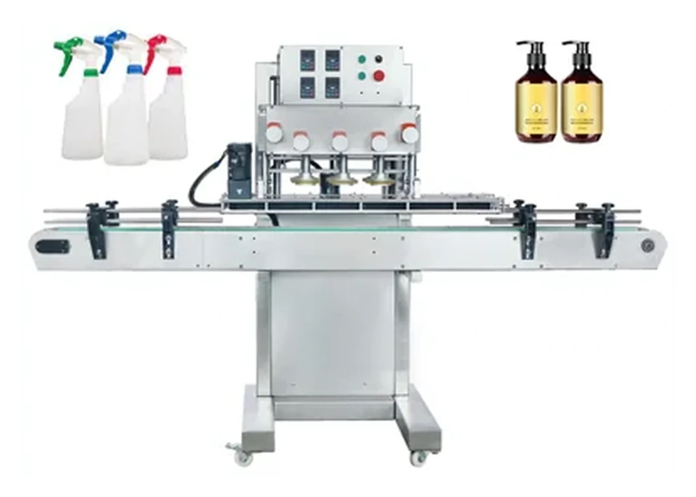
Automatic cappers
Inline cap tightening and cap feeding for higher-volume production.
Catalogue photograph; the required configuration is confirmed during quotation.
More about this machine familyScrew cappers
Torque-controlled tightening for threaded plastic and metal closures.
Catalogue photograph; the required configuration is confirmed during quotation.
More about this machine family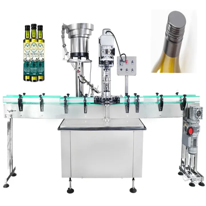
ROPP cappers
Roll-on pilfer-proof sealing for aluminium closures and glass bottles.
Catalogue photograph; the required configuration is confirmed during quotation.
More about this machine familyBuying checks
Accurate bottle machinery selection depends on the closure, bottle neck, bottle shape, fill product, speed target and the amount of manual handling that can remain in the process.
| Check | Why it matters | Details to send |
|---|---|---|
| Cap type | Semi-automatic machines can use chuck, ROPP, press or specialist heads depending on closure style. | Cap samples, bottle neck finish and closure notes. |
| Operator process | The safest loading method depends on bottle size, fill weight and production rhythm. | Current hand-capping method and expected operator cycle. |
| Batch variation | Frequent SKU changes need quick-adjust guides, tooling and documented settings. | Product list, cap families and bottle dimensions. |
| Upgrade path | Some semi-automatic processes can later feed into conveyor handling or automatic cap feeding. | Target future output and available floor space. |
More bottle capper pages
Use these crawlable pages to narrow the bottle capping machine route before sending samples or a project enquiry.
Inline cappers for higher output lines with cap feeding, conveyor control and repeatable tightening.
View pageChuck-head tightening for threaded caps where grip, cap profile and torque consistency matter.
View pageMachines for tightening screw caps, rework, batch production and improving closure repeatability.
View pageBottle cappers specified around torque range, cap material, thread engagement and bottle stability.
View pageCappers for ROPP, tamper bands, pilfer-proof closures and controlled seal presentation.
View pageCappers for lotion pumps, sprays, trigger closures, flip tops and personal care containers.
View pageBottle capping lines for household, industrial and chemical products with robust cap handling.
View pageCapping machinery for oils, sauces, drinks, glass bottles, plastic bottles and closures.
View pageHealthcare and technical bottle capping with repeatability, hygiene and line integration in mind.
View pageContinuous bottle cappers for conveyors, cap feeders, automatic tightening and integrated production flow.
View pageFAQs
Yes, they can be a practical step up from hand tightening when repeatability and operator comfort are becoming important.
Often yes, provided the neck, cap type and tooling are compatible. Change parts or chuck inserts may be needed.
It is normally slower than a fully automatic line because the operator still loads bottles or caps, but it can be much more consistent than hand tightening.
Send bottles, caps, filled weight, target output, torque or seal requirement and photos of the current packing process.
Send bottle and cap details, line speed target and photographs of the current production area. Lancing can advise on the most suitable bottle capping machine, cap feeder or complete line route.
Controlled batch capping
Most semi-automatic systems rely on an operator to load the bottle, place the closure or perform both tasks. The machine then controls bottle holding and the capping cycle. A fair comparison therefore includes ergonomics, loading rhythm, changeover and quality checks as well as the machine cycle.
| Area | What to define | What to observe |
|---|---|---|
| Operator loading | Who presents the bottle and cap, from which containers, at what working height and for what batch duration? | Reach, repetitive motion, safe hand position, placement consistency and achievable rhythm over time. |
| Bottle fixture | Clamp, nest, base support, neck support or guide requirements for every agreed format. | No bottle rotation, collapse, marking or variable cap position during the capping cycle. |
| Capping tooling | Chuck or insert, head height, torque method, top pressure and format-specific settings. | Thread engagement, cap height, torque or opening result and absence of closure damage. |
| Cycle control | Foot pedal, sensor, automatic cycling or guarded two-hand arrangement where applicable. | Repeatable cycle initiation, safe operation and no incentive for unsafe workarounds. |
| Batch output | Accepted bottles per batch or hour including normal loading, replenishment and first-off checks. | Sustained operator-and-machine performance rather than the fastest isolated cycle. |
Reference semi-automatic route
| Published item | Reference value | Production confirmation |
|---|---|---|
| Bottle height | 100–300 mm | Confirm fixture access, bottle rigidity and neck position for every format. |
| Cap diameter | 20–60 mm | Confirm cap profile, thread, height, material and the correct chuck or insert. |
| Working speed | 20–60 bottles/min, format-dependent | Measure a representative operator cycle and accepted output over a useful batch. |
| Operation | Manual or automatic cycling with bottle clamping | Agree how the cap and bottle are presented, and the safe cycle initiation method. |
The reference source is the Lancing semi-automatic screw capper page. Final machine choice, tooling and performance must be confirmed from production samples and the agreed test.
Plan a scale-up route before purchase. Identify the output or labour threshold that would justify automatic bottle capping, and whether the present machine can later connect to a conveyor or whether a different capping architecture would be required.
Semi-automatic capper FAQ
The operator commonly loads the bottle, places the cap or performs both tasks, while the machine controls bottle holding and the tightening or forming cycle. The exact division of work should be confirmed for each machine.
Measure accepted bottles over a representative batch, including normal cap and bottle replenishment, first-off checks and the operator’s sustainable rhythm. Do not use only the head cycle time.
Often, but different closures may require chucks, inserts, fixtures, supports and settings. Each format should be listed and demonstrated; an adjustment range alone does not prove compatibility.
Review reach, working height, repetitive motion, cap and bottle presentation, foot-pedal position, hand clearance, batch duration and whether the operator can maintain quality without fatigue.
Some designs support optional conveyors or integration, while others are dedicated bench machines. The intended scale-up path should be discussed before purchase rather than assumed.
It becomes relevant when cap placement limits sustained output, orientation must be controlled, labour or ergonomics are unacceptable, or the capper is being integrated into a continuous line.
Operator-and-machine cycle
A semi-automatic bottle capper can deliver repeatable tightening while retaining flexible manual loading, but the operator remains part of the production system. A useful trial should include the way bottles and caps are supplied, the loading position, the first-off quality check, normal replenishment and the duration of a representative batch.
| Cycle task | Variation to examine | Machine or workplace implication |
|---|---|---|
| Collect and orient the closure | Cap nesting, mixed orientation, liners, tamper features, pumps, triggers or closures that do not stand securely. | May justify a presentation tray, controlled pick position or a move towards automatic cap feeding. |
| Present the bottle | Filled weight, slippery product, bottle flexibility, unstable base and neck position. | Determines the locator, nest, clamp, support and working height required for a repeatable cycle. |
| Place the cap | Thread start, cap height, asymmetry, dip tube, orientation and the risk of cross-threading before the head engages. | Can change the tooling, guide method, operator instruction and the suitability of manual placement. |
| Initiate the cycle | Foot pedal, sensor, automatic cycle or guarded control arrangement, depending on the supplied machine and risk assessment. | Affects hand position, rhythm, safe operation and the ability to maintain a consistent batch rate. |
| Inspect and discharge | Cap height, visible damage, orientation, torque or opening check, leakage and where the finished bottle is placed. | Determines the inspection frequency, table or conveyor arrangement and the true time per accepted bottle. |
| Replenish and change format | Cap and bottle supply, chuck or fixture changes, head height, cleaning and first-off approval. | Shows whether the quoted batch capacity remains practical over a normal production period. |
Scale-up decision
Semi-automatic equipment is often suitable when batches are varied, closures are placed easily and one operator can sustain the required output without excessive handling. A move to full automation becomes more useful when bottle spacing, cap orientation, repetitive loading or coordination with an existing line governs production.
Suitable where format changes are frequent, batch sizes are controlled and manual placement supports the required output safely and consistently.
A discharge table, short conveyor, bottle locator or improved cap presentation can remove a specific operator bottleneck without converting the whole process.
Consider the automatic bottle capper route where continuous bottle flow, automatic cap supply and line interlocks are required.
Record likely future bottles, closures, output and floor space so the present tooling and workflow do not obstruct the next stage of automation.
Compare the wider bottle capping machine range and use the quotation checklist to include operator tasks, batch data and every required format.
Batch-output evidence
A semi-automatic capper removes or controls part of the closing task, but the operator still presents the bottle, closure or both. Sustainable output therefore depends on the full work sequence, not only the powered tightening movement.
Record how bottles arrive, where closures are stored, how the operator identifies the correct format and whether filled bottles can be handled without spillage or contamination.
Confirm bottle support, cap placement, hand clearance, cycle initiation and the condition that prevents an incomplete or incorrectly positioned pack from being capped.
Include the first-off check and the normal inspection method for alignment, thread engagement, cap position, torque or opening behaviour.
Time a realistic format change, setting confirmation and recovery from a rejected cap or incorrectly presented bottle instead of measuring only uninterrupted good cycles.
Use production-intent packs and an agreed defect definition. The bottle and closure compatibility guide helps organise samples, while the accepted-output method can be adapted to a representative batch. When manual placement becomes the main constraint, compare an automatic capper and a tested cap-feeding route rather than assuming a faster capping head alone will deliver the required result.
Semi-automatic capper questions
A semi-automatic machine can provide controlled capping while leaving bottle and closure presentation with the operator. The complete operator cycle therefore belongs in the specification.
Measure the complete cycle: pick the bottle, present or place the closure, start the machine, remove the bottle, inspect as required and prepare the next pack. Include normal replenishment and handling, not only the powered capping stroke. The result should be expressed as accepted bottles over a representative period with the intended operator method.
Repeatability improves when bottle location, closure placement, cycle initiation, tooling contact, settings and acceptance checks are clearly defined. A fixture or guide may reduce variation, but the work instruction and training remain part of the process. Trial more than one competent operator where operator technique could influence the result.
Record the bottle and closure identity, fitted tooling, machine height, guides or supports, relevant pressure or torque setting, operator checks and approved first-off sample. Photographs can support the record when reference points are unambiguous. Use the capper settings guide for a structured setup sheet.
The capping stage becomes the constraint when manual presentation, capped-bottle removal or quality checking cannot keep pace with filling or downstream handling. Assess the whole operator cycle and the space available for short-term accumulation. Automation may solve the constraint, but only after the actual limiting task has been identified.
Operator-assisted capability
A semi-automatic capper can improve repeatability, but the operator still affects bottle presentation, cap placement, cycle initiation, inspection and replenishment. Capability evidence should therefore record the complete working method rather than only the powered head movement.
Define bottle pickup, cap placement, bottle location, hand or foot control, release, inspection and handling of failed packs. Use the same sequence during trials and production checks.
Sample across the batch and across normal operator work, not only the first easy bottles. Record stops, replenishment, fatigue-sensitive tasks and any rework that reduces accepted output.
Record the task that limits output, the cap and bottle handling difficulties, accepted quality, batch pattern and time spent on manual presentation. This identifies which part should be automated first.
Process capability and sampling Accepted output and losses Compare automation levels
Semi-automatic model shortlist
The LU-XG6100 and LU-XG60C represent different closure processes. One tightens a pre-threaded cap; the other forms an aluminium ROPP shell around a compatible bottle neck.
Automatic bottle clamping with an operator-presented bottle and pre-threaded closure.
Operator-fed aluminium closure forming with dedicated roller tooling.
Review the reference envelope and confirmation boundary for every documented route.
Capping decisions and practical evidence
A semi-automatic capper can be compared fairly only when bottle loading, cap presentation, removal, replenishment and quality checks are included in the same observation.
Record the complete task sequence using representative filled bottles and normal cap supply. Separate machine waiting time from operator work. The result identifies whether a better work arrangement, cap feeder or automatic line is the next meaningful step; it should not be extrapolated from the fastest isolated tightening cycle.