Cap feeding and orientation
Automatic cappers normally need a cap elevator, bowl feeder, chute or placement system matched to the closure geometry.
Automatic cappers
Inline automatic bottle cappers for production sites that need cap feeding, container control, repeatable tightening and integration with filling, labelling and conveyors.
Specification focus
An automatic bottle capping machine is usually specified when manual cap placement or hand tightening starts to limit line speed, closure consistency or operator safety.
Automatic cappers normally need a cap elevator, bowl feeder, chute or placement system matched to the closure geometry.
Side belts, starwheels, grippers, gating and conveyor spacing keep containers stable during tightening or sealing.
The capper should be matched to filler speed, conveyor height, labelling position, coding and packing flow.
Relevant equipment
These machine families are commonly reviewed when specifying automatic bottle capping machines for production lines.
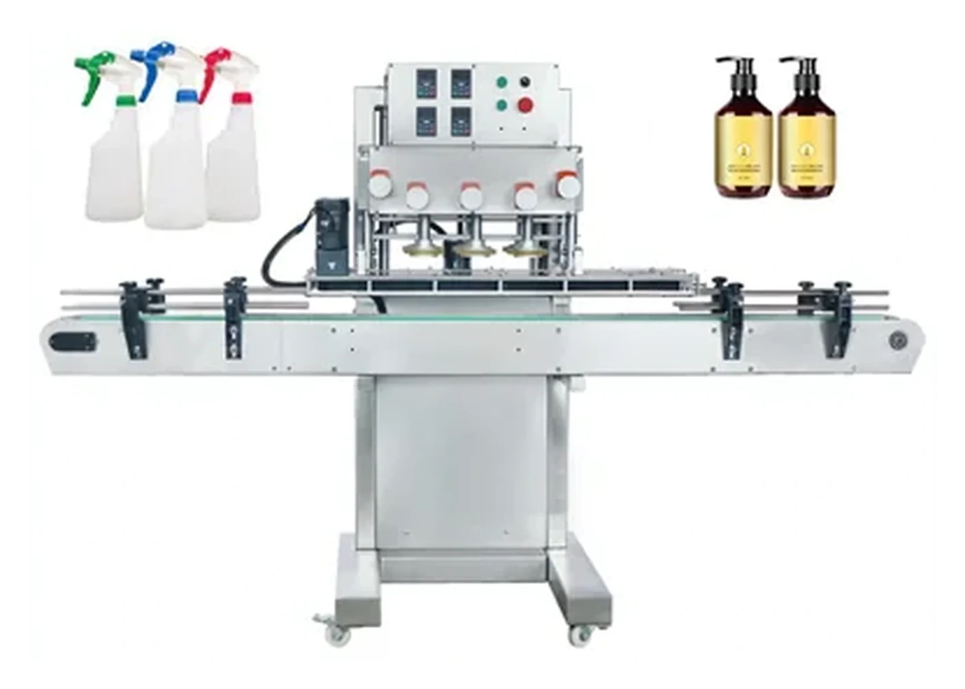
Automatic cappers
Inline cap tightening and cap feeding for higher-volume production.
Catalogue photograph; the required configuration is confirmed during quotation.
More about this machine familyScrew cappers
Torque-controlled tightening for threaded plastic and metal closures.
Catalogue photograph; the required configuration is confirmed during quotation.
More about this machine family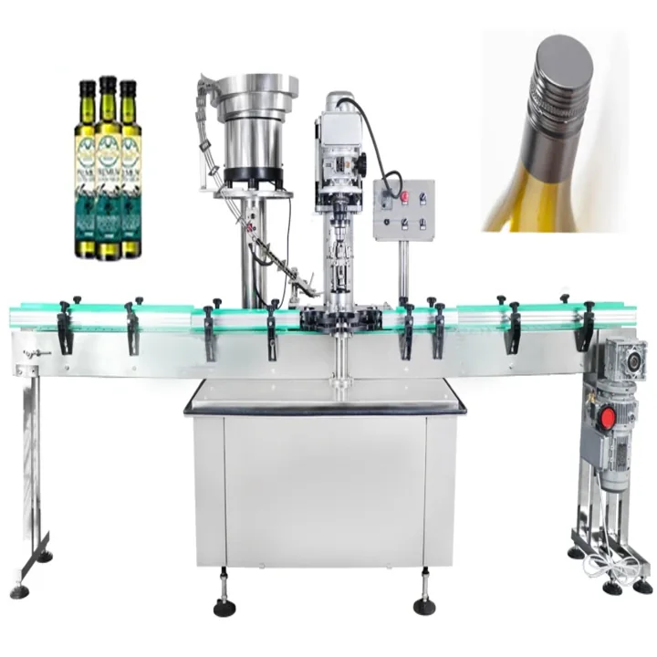
ROPP cappers
Roll-on pilfer-proof sealing for aluminium closures and glass bottles.
Catalogue photograph; the required configuration is confirmed during quotation.
More about this machine familyBuying checks
Accurate bottle machinery selection depends on the closure, bottle neck, bottle shape, fill product, speed target and the amount of manual handling that can remain in the process.
| Check | Why it matters | Details to send |
|---|---|---|
| Closure style | Different caps need different automatic capping heads and feeding methods. | Cap samples, neck finish, cap dimensions and closure drawings. |
| Output target | Line speed affects number of heads, conveyor design and whether cap feeding must be fully automatic. | Bottles per minute, batch size and shift pattern. |
| Bottle stability | Tall, light, shaped or small-footprint bottles may need extra control before torque is applied. | Bottle dimensions, fill level, material and photos. |
| Changeovers | A multi-SKU line needs tooling, guides and settings designed for repeatable changeover. | List of bottle sizes and cap families. |
More bottle capper pages
Use these crawlable pages to narrow the bottle capping machine route before sending samples or a project enquiry.
Bench and floor standing cappers for batch work, sampling rooms and controlled manual loading.
View pageChuck-head tightening for threaded caps where grip, cap profile and torque consistency matter.
View pageMachines for tightening screw caps, rework, batch production and improving closure repeatability.
View pageBottle cappers specified around torque range, cap material, thread engagement and bottle stability.
View pageCappers for ROPP, tamper bands, pilfer-proof closures and controlled seal presentation.
View pageCappers for lotion pumps, sprays, trigger closures, flip tops and personal care containers.
View pageBottle capping lines for household, industrial and chemical products with robust cap handling.
View pageCapping machinery for oils, sauces, drinks, glass bottles, plastic bottles and closures.
View pageHealthcare and technical bottle capping with repeatability, hygiene and line integration in mind.
View pageContinuous bottle cappers for conveyors, cap feeders, automatic tightening and integrated production flow.
View pageFAQs
Move to automatic capping when output, closure consistency or manual handling becomes a bottleneck. Cap feeding and conveyor control are usually reviewed at the same time.
Often yes, but tooling, guides, chutes and torque settings must be reviewed for each cap and bottle combination.
Some systems do and some are specified separately. For reliable automatic output, cap feeding, sorting and presentation should be designed with the capper.
Usually it can be considered, but conveyor height, spacing, controls, bottle stability and available floor space need to be checked first.
Send bottle and cap details, line speed target and photographs of the current production area. Lancing can advise on the most suitable bottle capping machine, cap feeder or complete line route.
Automatic capping performance
Removing routine manual placement increases the importance of cap feeding and line controls. The automatic machine should be assessed at the complete operating condition, including refilling the feeder, bottle variation, downstream stops and the method used to contain faulty packs.
| Function | Questions to answer | Acceptance evidence |
|---|---|---|
| Bottle infeed | How are bottles spaced, stabilised and detected? What happens with gaps, doubles or unstable containers? | Representative bottle flow through normal, starved and restart conditions without collision or uncontrolled release. |
| Cap feeding | How are caps loaded, oriented, buffered and recirculated? Which formats need dedicated tooling? | Sustained correctly presented cap rate, refill recovery, stop/restart and closure-condition inspection. |
| Cap placement | How is the cap transferred squarely to the neck, and how are pumps, triggers or unusual closures handled? | Placement accuracy, missed-cap response, thread start, tube condition and orientation where required. |
| Tightening or forming | Is the method chuck, clutch, spindle, servo, ROPP roller or another process? How is the bottle supported? | Cap height, thread engagement, torque or opening performance, leakage and visible condition. |
| Fault and reject handling | Which defects are detected, how is the line stopped or rejected, and how are events recorded? | Safe challenge tests using agreed sample faults where the relevant inspection or reject equipment is included. |
Sustained-output trial
Start from the agreed setup and document the format parts, recipe and initial quality checks.
Measure accepted bottles over the agreed duration using representative cap and bottle supply.
Replenish caps and bottles using the intended production method without staging an unrealistic test.
Include blocked, starved and short-stop recovery and observe cap buffer and bottle pressure.
Count defects and record torque, cap height, leakage, damage, alarms and intervention time.
Automatic does not mean universal. Format changes may involve chucks, spindle positions, bottle guides, star wheels, timing screws, neck supports, feeder tooling, tracks, escapements, sensors and stored parameters. The quotation should distinguish included formats from future engineering.
Compare cap feeding systems, integrated lines and the semi-automatic alternative. Use the quotation checklist to describe the required proof.
Automatic capper FAQ
In a fully automatic route, bottles transfer through the process and closures are normally supplied, presented and applied without routine manual cap placement. The exact loading and intervention tasks should still be stated.
No. A bowl is one option. Elevator, centrifugal sorter, cap chute, pre-oriented supply or specialist pick-and-place handling may be more appropriate depending on closure geometry, output and line arrangement.
Define which faults are detected, where detection occurs, whether the line stops or rejects, how confirmation is achieved and where rejected bottles go. Do not assume every capper includes inspection.
Cap feeding, bottle spacing, handling of unstable packs, inspection, accumulation, operator refill, downstream stops and changeovers can reduce sustained accepted output below an isolated capping cycle.
Demonstrate all mechanical parts and settings, feeder and track changes, recipe selection, first-off checks, safe access, cleaning and return to accepted production for each agreed format.
It may be preferable for smaller batches, frequent unusual changes, limited space or closures that are difficult to feed automatically. Compare total labour and batch completion time rather than assuming more automation is always better.
Automatic recovery states
Automatic capping output depends on how the system behaves between steady production runs. Bottle gaps, low cap levels, a blocked downstream machine or a short operator intervention are normal events. The project scope should define how the capper contains these conditions, what the operator must do and which checks are required before production resumes.
| Operating state | Expected machine behaviour | What to observe during testing |
|---|---|---|
| Starved bottle infeed | The capper should avoid presenting or applying closures where no correctly positioned bottle is available. | Sensor response, cap handling, bottle spacing and a controlled return to normal flow when supply resumes. |
| Low or interrupted cap supply | The machine should provide a clear response before the placement point becomes unreliable. | Low-level indication where included, remaining buffer, feeder recovery, incorrect caps and operator replenishment access. |
| Blocked downstream equipment | The capper and upstream equipment should stop in the agreed sequence without excessive bottle pressure or uncontrolled closure release. | Accumulation, interlock timing, bottle contact, cap buffer condition and restart without a surge of faulty packs. |
| Missing or badly placed cap | The included detection, stop or reject method should respond according to the agreed project boundary. | Challenge samples, false accepts, false rejects, safe removal and the status presented to the operator. |
| Emergency or guarded stop | Motion should stop safely and the restart sequence should not create an unexpected bottle or cap movement. | Position of bottles and caps after the stop, reset requirements, clearance of partial cycles and first-off checks. |
| Format restart | The machine should resume from the recorded mechanical settings or recipe after the agreed changeover and approval steps. | Correct change parts, guide positions, head settings, feeder setup, first-off quality and repeatability of the documented procedure. |
Controls and line ownership
An automatic capper rarely operates in isolation. The quotation and layout should identify who supplies the bottle-ready signal, how the capper reports ready, fault and blocked conditions, where accumulation is permitted and which machine controls any reject or downstream stop. Clear ownership reduces duplicated sensors, missing interlocks and ambiguous commissioning responsibilities.
Confirm how bottles leave the filler or infeed conveyor, the expected pitch and whether the capper can request a controlled pause.
Define the useful ready, running, low-cap, fault, blocked and changeover states and how they are displayed or exchanged where integration is included.
Identify the labeller, inspection, coding or packing constraint and the accumulation available before the capping stage must stop.
State which defects are detected, whether the response is a stop or reject, where rejected bottles go and how the event is confirmed.
Automatic cap presentation should be assessed through the cap feeder and recovery test. For multi-machine projects, use the filling and capping line guide and record the interface scope in the quotation checklist.
Automatic-line behaviour
An automatic capper may be mechanically capable of applying the closure while still losing production through poor cap supply, unstable transfers or unclear control responsibility. The useful specification therefore describes what the line does when it is running normally and when a common disturbance occurs.
| Production state | Required behaviour to agree | Evidence during testing |
|---|---|---|
| Starved | The capper pauses or reduces demand without creating gaps that cause incorrect cap placement or unnecessary rejects. | Controlled stop and restart after the upstream supply returns. |
| Blocked | Bottles are retained or released safely when downstream capacity is unavailable. | No uncontrolled pressure, unstable bottles or loss of pack traceability at restart. |
| Cap low or cap absent | The agreed alarm, warning, stop or controlled run-down occurs before uncapped bottles pass unchecked. | Normal replenishment and recovery are included in the run, not excluded from the demonstration. |
| Reject full or inspection unavailable | The line response and operator action are defined rather than left to informal intervention. | The reject boundary, reset permissions and restart sequence are demonstrated. |
| Fault cleared | The line resumes from a known state without unexpected bottle or closure movement. | A representative recoverable fault is cleared using the agreed operator procedure. |
Develop the state sequence with the bottle-capping controls and interlocks guide. Use the cap-feeder acceptance test for closure supply, the buffering guide for physical separation and the output-validation guide for the final production test.
Automatic capper questions
Automatic operation includes controlled stopping and restarting, not only continuous running. The answers below clarify the evidence that should accompany a line-speed claim.
The required behaviour should be defined for bottles and closures already between sensors, guides, feeder tracks and capping heads. The operator needs a known method to identify incomplete cycles, clear unsafe or doubtful packs and restart without releasing a surge of unverified bottles. The exact sequence depends on the machine and risk assessment, so it should be tested as part of the agreed fault-recovery plan.
Where reject confirmation is included, the controls should distinguish detection from successful removal. The project should define the reject location, confirmation method, full-bin or blocked-reject response and treatment of any bottle that cannot be reconciled. Those boundaries belong in the controls specification and the production quality record rather than being assumed from the presence of a sensor.
Useful triggers include a format change, tooling adjustment, feeder intervention, component batch change, extended stop, jam clearance or any event that could alter placement or torque. The approved triggers and checks should be recorded in the operating procedure. The quality-log guide provides a practical record structure.
Record the pack format, component batches, machine configuration, run window, accepted output, rejects by reason, cap replenishment, stops, adjustments and quality results. Data is useful only when it can be traced to the exact bottle-and-closure combination and the event that changed the process. Avoid collecting isolated counters with no agreed interpretation.
Automatic-line evidence
Automatic equipment should be evaluated through normal cap replenishment, bottle gaps, blocking, rejects, faults and restart—not only a short uninterrupted cycle. The operating record should identify which system state caused each lost or uncertain bottle.
Include capper readiness, feeder availability, bottle flow, micro-stops, rejects, changeover, first-off approval and external starved or blocked states. Keep the event detail behind the percentage.
Identify bottles between the last verified good point and the first accepted pack after restart, then reject, quarantine, rework or reinspect them under the approved site procedure.
Retain head or station identity where practical, sample through time and compare common pack variation with one-head or one-path behaviour.
Measure OEE and downtime Define start, stop and restart Plan capability evidence
Automatic model shortlist
A model shortlist should separate continuous spindle tightening, indexed single-head capping and rotary multi-head ROPP forming. Each route places different demands on bottle control, cap presentation and line interfaces.
Continuous side-belt bottle handling and progressive screw-cap tightening.
Indexed bottle detection and single-head capping with optional bowl or elevator.
Automatic rotary forming of compatible aluminium closures.
Capping decisions and practical evidence
An automatic capper reduces a defined set of operator tasks; it does not automatically eliminate replenishment, inspection or changeover work.
Count the paid work that the proposed system will actually remove after feeder loading, quality checks and finished-pack handling are included. Keep released capacity separate from cash savings. Where the project also introduces a new closure, validate that closure first rather than assuming the original rate and tooling will remain suitable.