Feeding is often the bottleneck
A fast capper cannot run reliably if caps arrive incorrectly, inconsistently or too slowly.
Cap feeding
Cap feeding equipment for lifting, sorting, orientating and presenting closures to automatic bottle capping machines.
Specification focus
Use this page to narrow the specification around this bottle machinery family before requesting a quote.
A fast capper cannot run reliably if caps arrive incorrectly, inconsistently or too slowly.
Simple screw caps may suit bowl feeding or elevators, while pumps, triggers and awkward closures often need more specialist handling.
The feeder, chute, pick-and-place route and capping head should be specified as a complete system, not separate items.
Relevant equipment
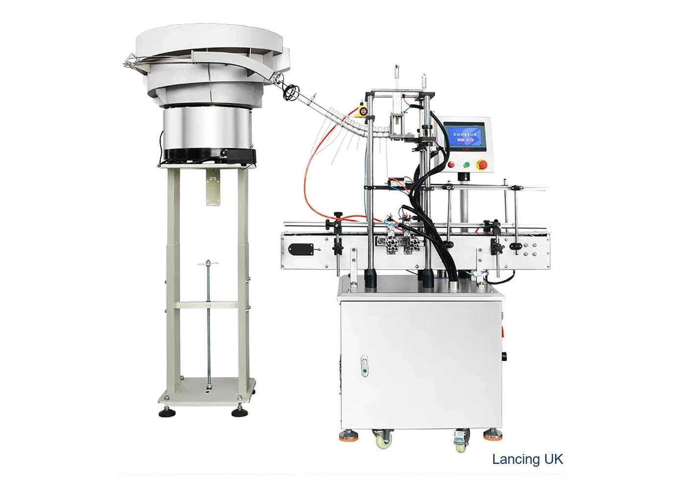
Cap feeding
Automated cap presentation and tightening for threaded caps where manual cap placement would restrict throughput.
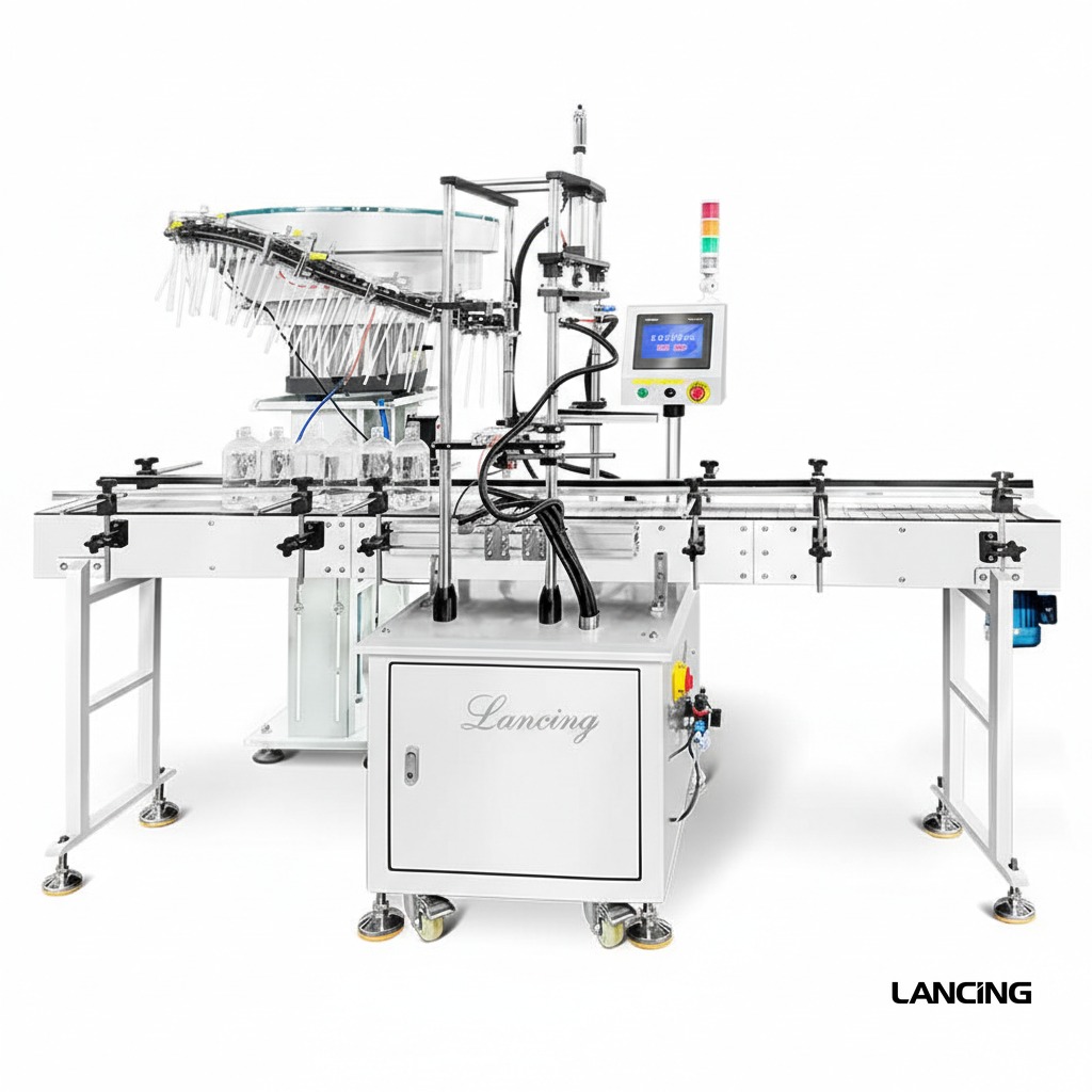
Cap feeding
Dedicated pump cap feeding and presentation equipment for closures that cannot be treated like simple screw caps.
Before you ask for a quote
For an accurate recommendation, supply bottle and closure samples or photographs, target output, batch sizes, fill product, bottle dimensions, cap dimensions and notes on any existing line equipment.
| Closure / cap type | Typical machine route | Specification checks |
|---|---|---|
| Threaded plastic screw cap | Screw capper, chuck capper, belt or spindle capper | Torque repeatability, cap height, bottle grip, thread start, changeover time |
| Aluminium ROPP closure | Semi-automatic, automatic or multi-head ROPP capper | Bottle neck finish, skirt length, tamper band, glass stability, roller tooling |
| Pump or lotion pump | Pump bottle capping machine with tube control | Dip-tube length, orientation, cap presentation, bottle stability, tightening torque |
| Trigger sprayer | Trigger sprayer bottle capping machine | Head orientation, tube handling, product sector, container neck and bottle shape |
| Push-on or snap cap | Press capping machine with cap feeder | Vertical force, closure fit, bottle support, cap nesting and feeder orientation |
FAQs
Most automatic systems need a controlled way to present caps. Some lines can use operator placement, but output and consistency are usually limited.
Sometimes, but it is better to plan cap feeding early so the capper, conveyor and layout are compatible.
Send bottle and cap details, line speed target and photographs of the current production area. Lancing can advise on the most suitable bottle capping machine or complete line route.
Closure supply and recovery
The feeder should separate bulk closures, reject or recirculate incorrect presentations, maintain a useful buffer and recover after normal replenishment or line stops. Its sustained performance must be assessed together with the capper and the actual production closures.
| Feeding route | Typical strength | Compatibility questions | Evidence to collect |
|---|---|---|---|
| Vibratory bowl | Sorts and orients many closures using a dedicated bowl and track. | Can caps separate without nesting, scuffing, bridging or unstable orientation? | Correct presentation, recirculation, jam rate, noise, cap condition and recovery across a sustained run. |
| Cap elevator | Lifts bulk caps and can reduce manual loading height or provide a simpler orientation route. | Does the cap geometry allow reliable pocketing, discharge and transfer to the chute or capper? | Fill-level behaviour, incorrect discharge, transfer stability and restart after depletion. |
| Centrifugal or rotary sorter | Can support higher-output applications with suitable cap geometry. | Are cap material, shape, orientation features and target speed compatible with the sorting principle? | Sustained accepted-cap rate, cap damage, false accepts and changeover evidence. |
| Manual cap placement | Low tooling complexity for batches, trials and difficult closures. | Can the operator sustain the target safely and consistently without becoming the line constraint? | Representative operator cycle, ergonomics, staffing, cap-placement quality and batch completion time. |
| Pick-and-place presentation | Useful for pumps, triggers or closures needing controlled orientation and insertion. | Can the feeder present the body and any dip tube without damage or loss of orientation? | Tube condition, placement accuracy, orientation, missed picks and stop/restart recovery. |
Feeder acceptance test
Load a representative quantity and observe nesting, bridging, tangling and surface damage.
Measure accepted caps delivered to the capper, not only feeder vibration or elevator movement.
Add closures using the intended production method and confirm that the line remains controlled.
Exercise blocked, starved and short-stop conditions and check buffer and recirculation behaviour.
Check marking, deformation, liner displacement, tube damage and incorrectly presented parts.
For a trigger-specific feeder, the current Lancing LU-XG446S reference publishes an approximate Ø15–35 mm cap range, bottle height around 10–280 mm and 20–25 bottles/min, subject to actual closures and transfer design. See the first-party trigger feeder page.
Identify bowl or elevator tooling, tracks, air jets, sensors, escapements, grippers, tube guides and capper transfer parts for every agreed format. Link feeder requirements to the machine range and include them in the quotation checklist.
Cap feeder FAQ
No. Height, mass, external features, material, liner, centre of gravity, nesting, surface finish and the required orientation all affect whether a feeder can sort and transfer the closure reliably.
Useful capacity is the accepted, correctly oriented closure rate delivered to the capper under representative conditions. It should include normal recirculation, replenishment and short stops rather than only the sorter’s theoretical movement.
Packaging variation, static, deformation, surface finish, contamination, storage condition or dimensional tolerance can change bulk behaviour. Keep batch information and compare good and failed closures physically.
Depending on the design, change parts may include bowl tooling, elevator pockets, tracks, rails, air jets, sensors, escapements, chutes, grippers, pick heads and transfer components.
The buffer should support the agreed response to replenishment and normal micro-stops without creating excessive cap pressure or damage. It should be defined from the whole line behaviour rather than as an isolated volume.
Manual placement can be practical for low-volume batches, trials, frequent unusual formats or closures that are disproportionately difficult to orient automatically. Ergonomics and sustained labour demand should still be measured.
Disturbance-based feeder trial
A short run with carefully arranged closures does not show how a feeder will behave in production. The trial should use production-intent caps in the intended bulk condition and include the ordinary events that disturb orientation: filling the hopper, running at low level, stopping the capper, returning rejected caps and restarting after a jam or empty condition.
Add closures using the proposed production method and observe bridging, nesting, scuffing and the operator access required.
Measure correctly presented caps at the transfer point while the capper consumes them at the representative operating rate.
Allow the feeder to approach its normal refill point and confirm that orientation and delivery remain controlled.
Block and release the downstream demand, then observe cap pressure, track condition, recirculation and the return to stable delivery.
Inspect incorrectly presented, damaged or recirculated caps and agree the response to jams, mixed closures and depleted supply.
| Observed condition | Possible cause to investigate | Evidence to record |
|---|---|---|
| Caps nest or bridge | Skirt geometry, liner, tamper ring, static, bulk pressure or an unsuitable hopper and track arrangement. | Cap batch, fill level, duration, intervention, rejected caps and whether normal replenishment changes the result. |
| Incorrect orientation reaches the transfer | Orientation feature, tooling wear, track setting, speed, recirculation route or mixed cap variants. | Correct and incorrect presentation counts, where the error escaped and how the system responds. |
| Cap condition deteriorates | Excessive recirculation, contact surfaces, vibration, chute pressure or decoration that marks easily. | Before-and-after visual inspection, liner and tamper-feature condition and the number of recirculation cycles represented. |
| Supply collapses after a stop | Back pressure, blocked track, buffer design, sensor position or a restart sequence that releases caps too quickly. | Stop duration, cap position, recovery time, operator action and any faulty caps or bottles created after restart. |
| One format needs repeated adjustment | Shared tooling may not control every cap family, or the changeover procedure may be incomplete. | Format-specific parts, settings, change time, first-off checks and evidence from every closure included in the quote. |
Feeder and capper as one system
The useful feeder output is the rate of correctly oriented, undamaged closures arriving at the placement point, not the motion inside the bowl or elevator. Buffering can absorb short variations, but the feeder, chute, escapement and capper must be tested together so that a shortfall is not hidden until the line runs continuously.
Review the automatic capping controls where cap demand is linked to conveyor flow. Pumps and trigger sprayers require additional orientation and dip-tube evidence on the pump and trigger capping page. For a complete project, include feeder ownership and recovery tests in the line specification and the quotation checklist.
Feeder acceptance protocol
A feeder demonstration can appear successful while the bowl or elevator is full and the downstream demand is low. The acceptance test should expose the conditions that create real interruptions: mixed bulk orientation, depletion, replenishment, recirculation, a controlled stop and restart, and the agreed format change.
| Test phase | Action | Record |
|---|---|---|
| Representative bulk load | Load closures using the intended production method and quantity, including normal random orientation. | Damage, nesting, tube tangling, incorrect parts and time to stable accepted supply. |
| Steady demand | Run at the agreed capper demand through a meaningful window. | Accepted closures at transfer, rejected or recirculated closures and interruptions. |
| Low level and refill | Allow the feeder to reach the agreed low condition, replenish normally and continue the run. | Warnings, starvation, bridging, operator actions and time to recover stable supply. |
| Stop and restart | Pause and resume the feeder and capper in the agreed sequence. | Duplicate release, gaps, misorientation, trapped parts and required resets. |
| Format change | Change tooling, settings and stored parts using the proposed production method. | Parts changed, settings confirmed, clearance of old closures and first-off approval. |
The full sequence is set out in the cap-feeder acceptance test guide. Combine it with the controls and interlocks guide so cap-low, no-cap and restart states have a defined line response.
Cap feeding questions
Cap feeder reliability depends on the physical condition of the closures as well as the bowl, elevator, track and controls. The trial should reproduce normal loading, recirculation and refill conditions.
Storage and handling can affect cleanliness, deformation, static behaviour, nesting and friction between closures. Follow the closure supplier’s storage instructions and keep the trial batch traceable. The closure storage guide explains the checks to make before caps are loaded into the feeder.
Record the closure identity, feeder tooling, mechanical positions, relevant control settings, normal fill level, refill method, observed recirculation and the accepted discharge orientation. Photographs can support fixed reference points. Link the setup to a restart and low-level test so the record describes stable behaviour rather than one successful feed.
Closures can behave differently when the feeder is full, nearly empty or being replenished. A new batch may alter nesting, friction or orientation even when dimensions appear equivalent. Testing only a small hand-loaded quantity can miss the disturbance created by normal production refill and recirculation.
Useful evidence covers bulk loading, normal operating level, low-level running, replenishment, recirculation, starved and blocked conditions, stop and restart, misorientation handling and the resulting accepted bottles. Use the cap feeder acceptance test to define the sequence.
Feeder loss and fault evidence
A feeder may appear to run while the capper is starved, receiving damaged closures or stopping repeatedly. Link bulk load, orientation, recirculation, chute buffer, replenishment and restart events to accepted caps at the transfer point and accepted bottles downstream.
Record the feeder as its own cause when cap supply, orientation, refill, jam or recovery prevents the capper from running. Keep capper and downstream states so the same event is not counted twice.
Retain representative failed caps, note cap level and recirculation, track and tooling condition, settings, sensor state, duration and the action taken. Compare with an approved run before changing several variables.
Compare bulk behaviour, orientation, scuffing, chute travel, transfer and sustained delivery under the recorded approved setup, then confirm the capped-bottle result.
OEE and downtime analysis Structured fault investigation Validate a new closure source
Published feeder route
The LU-XG446S demonstrates why trigger heads and dip tubes need more than a generic bowl-capacity check. The model route is linked with the disturbance-based feeder acceptance process.
Published trigger, bottle, output and package references with clear trial limits.
Define orientation, replenishment, low-cap and restart evidence.
Compare the capper and feeder routes that can form a complete cell.
Capping decisions and practical evidence
Feeding a cap consistently is not enough when the cap also contains an attachment or vent. The delivered closure must retain the features required for the finished bottle.
Keep traceable samples from before loading and after normal feeding and recirculation. Examine the functional feature as well as orientation and discharge rate. Distinguish damage introduced in bulk handling from damage introduced at capping, so a setting change addresses the right stage.