Good fit
Round, stable bottles with pre-threaded caps, repeatable cap presentation and a conveyorised filling-to-labelling sequence.
Automatic spindle capper
An inline belt-and-spindle capping route for stable round bottles with pre-placed threaded caps and continuous production flow.
Direct model answer
The LU-XG440B-class capper uses side belts to control bottles and successive spindle contacts to tighten pre-threaded closures while the pack continues through the machine. It is aimed at higher-output inline duties where cap placement, bottle stability and conveyor flow can be controlled consistently.
The values below are current Lancing reference data for initial project screening. They do not prove that every bottle and closure inside a dimensional range will run, or that the published rate will be sustained on a different line. Lancing confirms the final configuration, tooling, utilities, output and acceptance method against representative production samples and the complete application brief.
Published reference envelope
Use these values to decide whether the platform merits a sample review. Unknown or project-specific items remain part of the quotation and trial process.
| Published item | Reference value |
|---|---|
| Model reference | LU-XG440B class |
| Machine route | Automatic inline belt / spindle screw capper |
| Published reference output | 3,000–5,000 bottles/hour, subject to bottle and cap behaviour |
| Bottle diameter | 35–120 mm |
| Bottle height | 60–200 mm |
| Cap range | Confirmed from closure samples and selected spindle/tooling configuration |
| Cap feeding | Optional elevator or vibratory bowl route |
| Electrical supply | 110/220 V, 50–60 Hz |
| Published power | 2 kW |
| Approximate overall envelope with cap elevator | 3453 × 1393 × 2243 mm |
Machine route
The image supports identification of the machine route. It does not establish suitability for a different bottle, cap, speed or line arrangement.
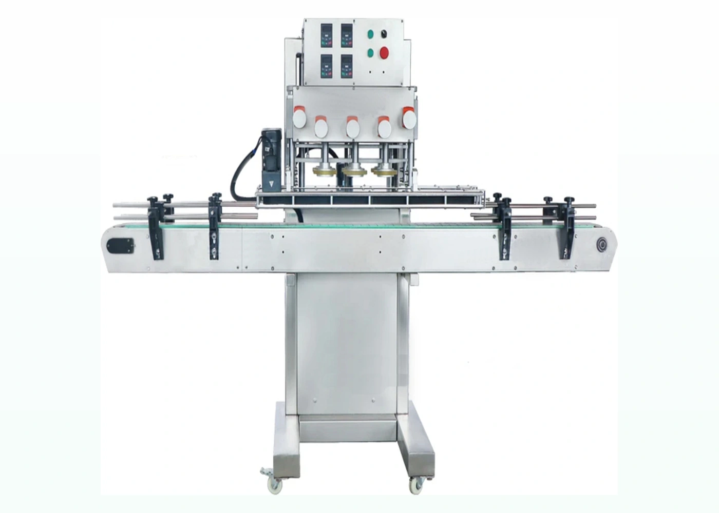
LU-XG440B class
Published first-party model image used as a visual reference. Final guarding, tooling and line arrangement are confirmed for the quoted machine.
Selection boundary
Spindle systems suit continuous screw-cap production when the cap is already placed correctly and the bottle can be held between side belts without distortion or rotation. They are not a substitute for reliable cap orientation or thread start.
Round, stable bottles with pre-threaded caps, repeatable cap presentation and a conveyorised filling-to-labelling sequence.
Lightweight containers, oval or highly tapered packs, caps with sensitive decoration, and formats where product contamination may reach the cap contact surfaces.
A chuck or indexed single-head machine may be preferable when closure geometry needs controlled top engagement, bottle shapes are difficult for side belts or batches change frequently.
Production evidence
A spindle capper can only tighten the closure presented to it. The line trial should therefore include cap feeding or manual pre-placement, the transfer into side belts, progressive contact, release and downstream accumulation. Record every high, skewed, cross-threaded or cosmetically marked closure rather than reporting speed alone.
Confirm orientation, chute handover, low-level behaviour and refill recovery using production closures.
Check the full bottle range at steady state and after stops, including the least stable filled format.
Set height, pressure and contact sequence so the cap tightens without damage or bottle distortion.
Prove starved, blocked, stop, restart and accumulation conditions with adjacent machinery or a representative simulation.
Quotation and trial brief
A useful quotation should describe the operating duty and acceptance evidence, not only the nominal bottle and cap diameter.
Provide filled production bottles, every closure variant, component drawings where available, product condition and the least stable or most difficult format.
State required accepted output, batch size, shift pattern, changeover frequency, operator tasks and whether cap placement is manual or automatic.
Provide the layout, conveyor direction and height, available space, utilities, connected machinery, control requirements and the quality checks used to release the finished pack.
Buyer questions
These answers clarify the model boundary before a formal sample and project review.
A spindle capper uses successive rotating contacts while the bottle travels through the machine. A chuck capper grips the closure from above, normally at one indexed station. The best route depends on closure geometry, bottle control, output and changeover requirements.
The capping machine can be paired with an elevator or vibratory bowl and a suitable handover system, but cap feeding is a closure-specific part of the project. The feeder should be trialled with normal production caps.
Bottle spacing, cap availability, stable thread start, side-belt grip, spindle settings, inspection, changeovers and downstream accumulation all affect accepted output. The final figure must be demonstrated with the intended line configuration.
Potentially, but side-belt pressure and the tightening reaction can deform or destabilise a lightweight pack. Filled samples at the intended temperature and product condition are needed to assess support and grip.